





Does your 15 kW pump run at full speed even when it doesn't need to? You waste energy and shorten pump life. A low voltage VFD solves this problem. It adjusts motor speed to match demand. But you must choose the right unit.
Three factors matter most. First, match the voltage. Your motor needs 380V~480V. A mismatch causes instability and overheating. Second, check the current rating. The VFD's output must equal or exceed your motor's Full Load Amps. Third, identify your load type. Centrifugal pumps need variable torque drives.
Get these decisions right. Your pump will run efficiently and last longer.
Key Takeaways
Make sure the VFD’s voltage and Full Load Amps match your motor’s exactly.
Use a variable torque VFD for centrifugal pumps to save energy and reduce heat.
Choose an enclosure that shields your VFD from dust, moisture, and excessive heat.
Choose sensorless vector control if you need strong starting torque and smooth operation.
Matching Low Voltage VFD Output to Motor Nameplate
Your motor's nameplate has all the info you need. Before buying any drive, find this metal plate and write down two key values: voltage and Full Load Amps (FLA). These numbers tell you which low voltage VFD will work safely with your pump.
Decoding Voltage and Current Ratings
The VFD's voltage rating must match your motor's winding voltage exactly. A 230V motor needs a 230V drive. A 460V motor needs a 460V drive. If these don't match, you get unstable operation, too much heat, and early motor failure. Common three-phase power choices include 220V, 380V, and 460V systems. Check your facility's supply voltage before you order.
Your 15 kW motor equals 20 horsepower. This matters because many makers list drives in horsepower, not kilowatts. When you look at the nameplate, find the FLA value. This number shows the most current your motor pulls when fully loaded. The VFD's continuous current rating must be equal to or higher than this FLA. Never pick a drive with a lower current rating than your motor needs.
Here's a real example. A 15 kW motor with a 30A FLA needs a drive rated for at least 30A continuous output. The GK3000-4T0150G model gives 32A at 380V~480V. This 2A extra gives a safety cushion for steady operation. Without this buffer, the drive runs at its max all the time, creating extra heat and shortening part life.
Understanding Variable Torque vs. Constant Torque
Centrifugal pumps create a variable torque (VT) load. This difference greatly affects your drive choice. A constant torque (CT) load, like a conveyor, needs the same torque at any speed. A centrifugal pump works differently. Its torque need drops with the square of speed. At half speed, the pump needs only one-quarter of full torque and one-eighth of full power.
This relationship changes how makers rate their drives. A VT load never pushes the drive with high current at low speeds. So, makers can give a higher horsepower rating to the same physical drive for VT uses. For example, a drive rated at 30 kW for CT loads might get a 37 kW rating for VT loads. The transistors face less heat stress because the load drops as speed goes down.
For your pump, pick a drive with a VT rating that fits your motor's horsepower. The drive's cooling system handles heat differently than it would for a CT use. Switching losses and heat rejection rise as speed falls. A VT-rated drive accounts for this, giving reliable operation across the whole speed range.
Your choice of low voltage VFD depends on these nameplate details. Take time to record the voltage and FLA values correctly. Compare them with the drive's specs. Confirm the VT rating fits your centrifugal pump. These steps prevent costly errors and keep your pump running well for years.
Selecting Low Voltage VFD Enclosures for Harsh Environments

The enclosure keeps your low voltage VFD safe from its surroundings. A clean room with controlled temperature needs little protection. A hot, dusty factory needs much more. Pick the enclosure that fits your actual site conditions.
Assessing Temperature, Humidity, and Altitude Limits
Heat is the biggest enemy of any drive. Most VFDs have a maximum air temperature rating of 40°C (104°F). Above that, the cooling system can’t get rid of heat fast enough.
Measure the real air temperature at the drive's air inlet. Don't trust the room thermostat. The air at the inlet can reach 48°C even when the room says 28°C.
Measure the air temperature right at the drive's air inlet vent.
Compare that number to the 40°C maximum rating.
If the inlet is too hot, add better airflow, add air conditioning, move the drive, or accept lower performance.
According to the Siemens technical manual, VFDs must run at lower power when air is above 40°C (104°F). In a hot industrial RO plant, instead of lowering power, the team installed a special AC system to keep the inside of the enclosure at 35°C. This kept the VFDs below the 40°C limit and let them run at full power without any loss.
Humidity causes a different problem. Warm, wet air hits cooler surfaces inside the cabinet. Water drops form on circuit boards and bus bars. This leads to rust, electrical leaks, short circuits, and early part failure. In very humid places, water problems cause about 30-40% of VFD breakdowns.
Five enclosure features help stop moisture damage:
Heating systems: Thermostats keep the inside warmer than the dew point.
Sealed designs: Gaskets block humid outside air.
Dehumidification: Desiccants pull moisture out.
Drainage systems: Channels handle water drips.
Insulation and coatings: Barrier materials stop cold spots.
Altitude also affects performance. The standard rating works up to 1,000 meters (3,280 feet) above sea level. Above that, thinner air lowers cooling ability. Subtract 1% for every extra 100 meters above the 1,000-meter starting point.
Choosing the Right IP Rating for Your Site
The Ingress Protection (IP) rating shows how well the enclosure blocks dust and water. Many 15 kW VFDs come standard with IP20 enclosures. This rating gives no dust or water protection. Dust builds up fast on inside circuit boards.
An IP54 enclosure works for normal factories with some dust. Filter material blocks most factory dust while still letting air flow.
Places that get washed down need even more protection. High-pressure cleaning makes strong water jets.
For high-pressure water spray, you need an IP66 (or NEMA 4) enclosure. IP66 enclosures stay watertight against strong water jets from any direction.
Your site conditions decide the right enclosure. Measure the air temperature at the inlet. Check the humidity level. Know your altitude. Identify the dust and water exposure. Then pick the IP rating that matches real life.
Identifying Essential Control Features for Pump Applications
Your control mode decides how well your pump handles changing needs. You have two main choices: V/F control and sensorless vector control.
Comparing Sensorless Vector and V/F Control
V/F control keeps a fixed voltage-to-frequency ratio. It works fine for simple, fixed-speed jobs. But it cannot give high starting torque at low speed because it does not know the rotor position when stopped. Your pump may have trouble starting at low speeds.
Sensorless vector control fixes this issue. It figures out rotor flux and sends the right current vector. This gives strong starting torque without an encoder. After setup, it provides full torque from very low speeds.
This feature is available on many drives, including those for 15 kW pumps. Sensorless vector keeps steady torque at low speeds, where V/F control becomes shaky. For centrifugal pumps, sensorless vector boosts low-speed torque and saves energy.
PID control adds more value. VFDs take feedback from a sensor and change motor speed to reach a target setpoint.
The built-in PID controller reads feedback signals straight from pressure transmitters. It finds the gap between actual and target pressure. The drive then changes output frequency to smoothly adjust pump speed.
Prioritizing Overload and Safety Protections
Your low voltage VFD must guard both itself and your motor. Thermal overload protection watches current, voltage, and frequency all the time. Phase loss protection spots missing phases on its own. Overvoltage and undervoltage protection shield against power supply changes.
To prevent overvoltage faults, apply conservative deceleration ramps when using a VFD for motor control.
A separate fuse or breaker is still needed upstream for short-circuit protection. But the VFD can take the place of a standalone overload relay. PID control removes electrical stress from inrush current, mechanical stress on bearings and seals, water hammer from pressure spikes, unstable control, and warranty risks from going over starts-per-hour limits.
Planning for Future Scalability and Communication Needs
A 15 kW pump installation often grows over time. You may add extra pumps, change operating conditions, or connect to a building management system. Your VFD choice today must support these future needs. Two factors matter most: current headroom and communication ability.
Sizing for Headroom and Future Loads
Select a drive with extra current capacity above your motor's Full Load Amps. This headroom protects against unexpected load spikes and supports future pump upgrades. Industry guidelines recommend 10-20% headroom for durability and operation under varying loads.
Sizing guideline: Select a VFD with 10-20% headroom above the motor's FLA to ensure durability and operation under varying loads. This headroom supports future scalability, as a scalable VFD accommodates increasing load demands, future integration of automation systems, and enhanced energy efficiencies. The recommendation ensures the drive remains useful even when operating needs change, supporting system growth without requiring immediate replacement.
A 32A drive for a 30A motor gives only 7% headroom. For true scalability, select a drive with a higher current rating, such as one providing 10-20% headroom. This extra capacity lets you add pump stages, handle seasonal demand changes, or run the drive at lower temperatures for longer life. A properly sized drive stays in service longer and reduces replacement costs.
Ensuring Programmability and Protocol Compatibility
Modern pump systems need communication. Your low voltage VFD must include communication ports for integration with PLCs, SCADA systems, or building management systems. Choose a drive that supports the communication protocol used in your facility. For most systems, a drive with built-in serial or Ethernet communication provides sufficient functionality. Some drives offer option cards for protocol conversion. Verify this capability before purchase to avoid costly adapters later.
Implementing Best Practices for Installation and Maintenance
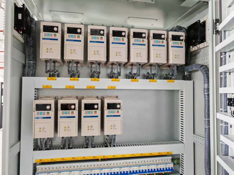
Wiring, Grounding, and Shielding for Noise Immunity
Good wiring and grounding keep your VFD safe from electrical noise and false trips. Your drive connects to sensitive SCADA and instrument networks. These networks pick up noise without proper shielding. Special VFD cable with a continuous shield stops this problem.
In water and wastewater pump stations, SCADA and instrument networks are very sensitive to electrical noise. Using special VFD cable with a continuous shield is the best choice over regular power cable. The small extra cost is worth it because you avoid troubleshooting, bearing failures, and rewiring costs.
The shield must connect at both the drive and motor ends. Use 360-degree EMC cable glands for this hookup. This method gives low resistance at high frequencies. The common pigtail method bunches the shield braid into one wire tail. Tests show this adds inductance and creates ground currents equal to unshielded wire.
The chassis ground hookup needs a braided cable ground strap, not panel screws. Galvanic action, rust, and dirt cause resistance buildup over time.
The chassis ground hookup from the control panel to the frame should use a braided cable ground strap, not panel screws. Screws and bolts don't always make good electrical connections because of galvanic action, rust, and dirt, which can cause strange errors and problems as the system gets older.
Every ground hookup must run alone to a shared ground bus in a star layout. Daisy-chaining creates shared-resistance coupling that pushes noise between drives. For submersible pump setups, figure out the longest cable length based on your VFD output and motor needs. Undersized cable causes voltage drop that lowers motor torque and triggers false trips.
Establishing a Routine Maintenance Schedule
Regular care keeps your VFD running well for years. Cooling fans and air filters need the most attention. Dust buildup blocks airflow and makes internal parts overheat and fail early.
Use low-pressure compressed air to clean heat sinks. Make sure fans spin freely in the right direction. Watch the air temperature around the enclosure. Periodically, check torque on all power terminals. Loose connections create heat and cause random faults. Write down each inspection with setting readings to spot drift before failure happens.
Use these five steps to pick your low voltage VFD. First, make sure the voltage and current ratings match your motor's nameplate. Second, pick an enclosure that fits your site's conditions. Third, choose sensorless vector control for better torque at low speed. Fourth, plan for 10-20% more current than your motor's FLA. Fifth, install with good wiring, grounding, and regular maintenance.
A 15 kW (20 hp) drive is a big investment. If you skip any step, you risk early failure or poor energy use. Each choice depends on the one before it.
Talk to the technical team to check your motor's nameplate info. Ask for a custom recommendation for your pump use.
FAQ
What happens if I choose a VFD with the wrong voltage rating?
A mismatched voltage leads to uneven motor operation and too much heat. Your motor may run oddly or break down too soon. Always check your motor's nameplate voltage with the VFD's input voltage before you buy.
How much current headroom should I select above my motor's FLA?
Industry rules suggest 10-20% extra capacity above your motor's Full Load Amps. This buffer allows for future pump upgrades, manages unexpected load changes, and lowers heat pressure on the drive's inside parts.
Can I use a constant torque VFD for my centrifugal pump?
Yes, but you will pay for capacity you don't need. Constant torque drives have higher overload ratings than variable torque drives. A VT-rated drive fits your pump's drop in torque need at lower speeds, giving good performance at a lower cost.
What IP rating do I need for an outdoor pump installation?
Outdoor setups need at least IP54 for dust and splash safety. If your site has strong water cleaning, choose IP66 or NEMA 4 rated enclosures. These can handle strong water sprays from all sides and keep moisture out.
Do I need special cable for my VFD installation?
Yes. Use VFD-rated wiring with a full shield for motor wires. Standard power cable does not have good shielding, which lets in electrical noise that causes false shutdowns and bearing breakdown. Attach the shield at both ends using full-circle EMC connectors for best noise protection.
Previous:
Next:
Sign up for updates