




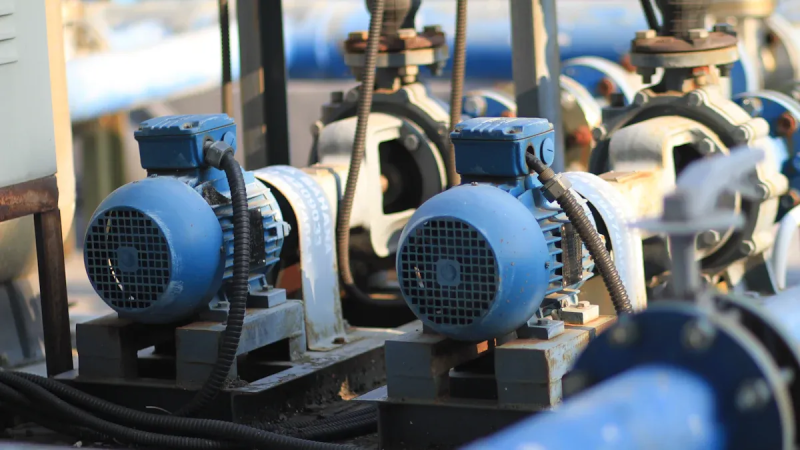
Centrifugal pumps often waste power when controlling liquid flow. Standard mechanical valves squeeze the flow, which leads to high power costs and bad equipment wear. You can fix these hard operating problems by using a pump VFD. A VFD changes the motor speed to meet exact fluid needs without wasteful valve squeezing. This smart motor control stops harmful water hammer damage and removes shaky flow problems in your piping system. Modern Canroon pump VFD technology offers smooth machine startup and big power savings for your factory work. Using a dependable Canroon pump VFD protects mechanical parts while boosting your total long-term working efficiency.
Key Takeaways
Variable Frequency Drives adjust how fast a motor turns to fit exact fluid movement needs.
A VFD lowers energy costs by slowing down the motor instead of closing valves.
Small drops in pump speed create massive energy savings for your facility.
Soft starts prevent electrical damage by increasing motor speed slowly and smoothly.
Slow stops prevent water hammer shocks and protect your pipes from getting damaged.
Sensors send fast live info so the VFD changes pipe pressure by itself.
Canroon VFDs detect low liquid levels and turn off to stop motor damage.
How a Variable Frequency Drive Works with Centrifugal Pumps
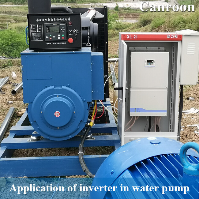
You can control your pump flow easily by learning about electric power conversion. A variable frequency drive turns standard wall electricity into a flexible power supply. This supply changes motor shaft speed without creating physical stress. Centrifugal pumps run best when you match electrical input to your actual fluid needs.
AC-DC-AC Power Conversion Basics
Electrical power changes through three clear steps inside the drive circuit.
Rectification of Incoming AC Power
Your power company sends three-phase alternating current electricity to your facility. This incoming electricity switches its direction constantly at a set grid speed. A vfd takes this alternating current using special diode bridges or solid-state switches. These electronic parts work like one-way gates for your electrical current. They force the electricity to move in only one single direction. This process changes the alternating voltage into a direct current supply. Standard rectifiers turn three-phase power into steady one-way current very quickly. You prevent big power losses when starting large equipment with correct rectification.
Adding a VFD to a motor improves its power factor. Most VFDs run at a 0.96 power factor, which easily beats the standard utility goal of 0.90. VFDs usually raise the overall power factor on AC induction motors. Standard low-voltage VFDs reach a 0.96 power factor, which is higher than most AC motors can manage.
DC Bus Filtering and Voltage Smoothing
The electricity coming out of the rectifier stage is still messy. It has big voltage bounces and unwanted electrical noise. You must have a steady voltage source to run your motor safely. The direct current bus area fixes this problem with large capacitors and heavy inductors. Capacitors store extra electrical energy and smooth out small voltage drops. Inductors stop fast changes in the main electrical current. Together, these internal parts clean up the raw direct current. The bus keeps a flat DC voltage level under changing work conditions. The system stores this power safely before sending it to the final circuit. Good filtering guards weak output transistors from damaging voltage spikes. This clean direct current helps internal power parts last a very long time.
IGBT Inversion via Pulse Width Modulation
The solid-state inverter forms the last power step inside a vfd. High-power insulated gate bipolar transistors turn the clean direct current on and off super fast. The inverter uses PWM to build a flexible voltage and frequency output from flat DC power. Transistors switch back and forth quickly using timed electrical pulses. The motor coils act like a filter, turning these fast pulses into a smooth electrical wave. By changing pulse sizes in a smooth wave pattern, the output acts like standard AC power to control voltage and frequency. This step finishes the whole power conversion process safely.
Speed Regulation Mechanics
Modern drives adjust liquid flow by changing output electrical frequencies directly to match system needs.
Maintaining Constant Volts-per-Hertz Ratio
An electric motor requires balanced magnetic forces to run well under changing work loads. The vfd control system keeps a steady ratio between voltage and frequency to hold motor force firm. Centrifugal pumps need changing force levels, so the turning power requirement goes up as speed increases. The steady ratio matches this pattern well to ensure smooth turning force. The drive maintains steady magnetic field strength by holding the V/f ratio constant. For centrifugal pumps, required turning force moves with the square of motor speed. At half speed, turning force drops to 25 percent, so motor power reduces automatically. This steady ratio lets the motor supply required turning power without getting too hot.
Dynamic Frequency Adjustment
Standard single-speed motors turn at full power all the time. A variable speed drive lets you change output frequency right away to adjust pump work. Changing electrical frequency shifts pump output without placing extra flow valves in your fluid pipes. You get exact flow control by using automatic updates inside your drive system. Dropping the operating frequency lowers total electricity use by a large amount. Plant workers control liquid speed directly while holding stable pressure across the entire pipe network. You skip manual valve settings because the drive changes motor speed automatically from sensor signals. A vfd system gives you full control over fluid movement without wasting power.
VFDs work by changing the frequency and voltage of the electricity sent to the pump motor. This action gives exact control over shaft speed, letting workers adjust pump work fast to match real-time needs. Old systems run pumps at maximum speed and choke liquid flow with valves. In contrast, a VFD changes motor turning speed smoothly to give the exact flow and pressure you need.
Energy Efficiency and Advantages of a Pump VFD
You can lower operational costs by matching equipment performance to real demand. Installing a vfd unlocks major process improvements across fluid operations. Understanding basic hydraulic laws helps you maximize your system performance.
The Affinity Laws and Power Savings
Mathematical rules describe how centrifugal pumps operate under changing conditions. These rules show direct links between turning rate, pressure, and power intake. System operators rely on a vfd for precise control.
Flow Rate Proportional to Speed
Liquid movement scales directly with shaft rotation. You cut output volume in half when you lower shaft rotation by half. This linear relationship means that matching pump speed to required flow rate eliminates excess fluid movement in system piping.
This direct relationship allows you to adjust liquid delivery accurately without guessing.
Head Pressure Proportional to Speed Squared
System pressure drops faster than pump flow when speed drops. A small speed reduction creates a larger drop in system pressure. A pump running at 80% speed produces 64% of its full head pressure. You must maintain enough rotational speed to overcome the fixed elevation lift of your piping system. Using a vfd keeps equipment running within safe hydraulic limits.
Power Consumption Proportional to Speed Cubed
Power needs change based on the third power of shaft rotation. Small speed reductions yield massive energy savings for your facility. Drive controllers with vfd technology optimize electrical consumption.
The affinity law states that power consumption changes with the cube of speed: P₂/P₁ = (N₂/N₁)³. Reducing speed by 20% cuts power by 49%. For example, a pump drawing 20 HP at 1750 RPM requires only 10.2 HP at 1400 RPM, demonstrating significant energy savings from modest speed reductions.
For a 22 kW centrifugal pump running at 50 Hz, reducing speed to 47 Hz gives a power ratio of (47/50)³ = 0.83. This drop results in power consumption of 18.26 kW and saves 3.74 kW, achieving a 17% reduction.
Pump VFD Efficiency Versus Mechanical Throttling
Traditional installations use mechanical control valves to choke liquid movement. Modern speed control offers superior overall energy efficiency.
Elimination of Control Valve Head Losses
Standard valves waste electricity by creating artificial friction in your pipes. A variable frequency drive changes output parameters directly to control flow.
You eliminate wasteful pressure drops by removing physical throttling valves from your fluid lines.
High Frictional Loss System Optimization
A vfd yields the highest efficiency gains in systems with long pipelines. Fluid movement through long pipes creates heavy friction losses and steep system curves. Lowering pump shaft speed reduces total dynamic head significantly in friction-dominated loops. In contrast, a vfd operating in high static lift setups has a narrow speed reduction range. Reducing speed too much leads to dead-head conditions where the pump cannot overcome the lift.
Mechanical Stress and Surge Reduction
Speed regulation protects physical equipment from extreme force and sudden impacts. Integrating a vfd prevents mechanical wear.
Soft Starting to Eliminate Inrush Spikes
Starting standard motors directly across utility power creates extreme mechanical stress. A variable frequency drive acts as a soft starter to ramp up shaft rotation safely.
High starting currents damage electrical supplies and cause sudden voltage drops.
Controlled acceleration over 5 to 20 seconds reduces peak inrush current by 50–70%.
Smooth torque delivery lowers stress on shafts, couplings, and pump bearings.
Water Hammer and Hydraulic Surge Mitigation
Abrupt stops create destructive pressure waves inside closed fluid lines. Modern vfd systems stop hydraulic shocks through managed deceleration ramps. The drive slowly decelerates the pump to reduce fluid velocity gradually. This controlled slowdown prevents back-pressure spikes and allows check valves to seat gently without slamming. Continuous vfd monitoring prevents system hunting during daily operations.
VFD Selection Criteria and Motor Compatibility
You evaluate electrical details before choosing equipment for your pump system. Proper equipment matching ensures high operational reliability and protects your financial investment.
Voltage Categories and System Sizing
System operators choose drive hardware based on plant infrastructure and motor sizes. You select the right voltage class to maintain balanced efficiency across your facility.
Low Voltage vs. Medium Voltage Drives
You match equipment voltage to your existing supply lines and motor specifications. The choice depends on power levels and utility access.
Peak Current and Torque Demands
You size a vfd by looking directly at continuous output current ratings instead of horsepower. Centrifugal pumps need a normal-duty rating with 110% overload capacity for 60 seconds. You account for site conditions during installation. Derate current by 1% per °C above 40°C ambient temperature. Derate current by 1% per 100 m above 1000 m elevation. This sizing strategy provides smooth motor control under heavy loads.
Inverter-Duty Motor Requirements
Standard motors fail under fast electronic switching. You need specialized motors to handle modern power supplies.
NEMA Insulation and Thermal Ratings
Solid-state switches create fast voltage risetimes. You protect motor windings from breakdown by using proper insulation standards.
NEMA MG1 Part 31.4.4.2 requires insulation systems for motors rated 600V or higher to withstand peak voltage spikes at least 3.1 times the rated voltage with a rise time of 0.1 microseconds or greater.
Low-Speed Heat Dissipation Factors
Standard fan-cooled motors rely on shaft-mounted fans for heat removal. Reducing motor speed lowers cooling airflow significantly. At 15 Hz, a standard fan delivers only 15% of its rated airflow. This reduced air movement causes rapid heat build-up under full torque. You monitor operating temperatures or install supplemental cooling fans to protect equipment. Proper vfd integration keeps thermal levels safe.
Harmonic Distortion and dV/dt Spikes
Fast output pulses create high voltage spikes across long lead wires. You apply proper filters to protect hardware when distances increase.
Install 3% or 5% line reactors on input sides to reduce harmonic distortion.
Add dv/dt output filters for distances between 100 and 300 feet to limit peak voltage.
Use sine wave filters for long cable runs over 1000 feet to eliminate spikes completely.
Selecting a quality vfd protects hardware. Proper vfd installation extends system life. Correct vfd settings prevent unexpected trips. Your vfd keeps fluid operations efficient. A reliable vfd improves factory safety. Your vfd controls system pressure. Proper vfd setups optimize facility power. Every vfd unit requires smart setup.
Control Strategies and Canroon Drive Features
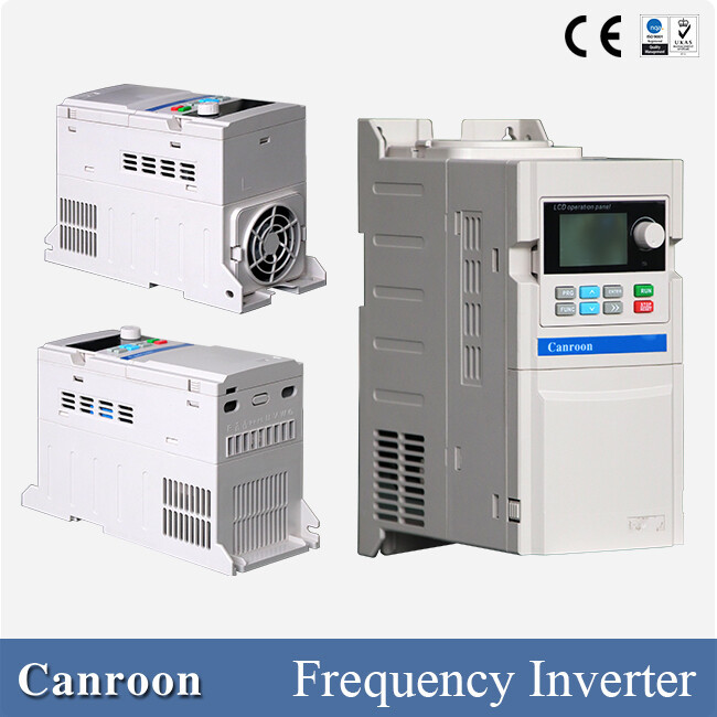
Advanced drive intelligence keeps modern industrial fluid systems running smoothly. You get precise process stability with digital software rather than manual settings.
Closed-Loop PID Control Strategies
Automatic feedback loops keep fluid processes steady when working conditions change. A drive uses live data to adjust machine output without any jerky movements.
Constant Pressure and Flow Transducer Feedback
You keep exact pipe pressure by placing physical transducers in your pipe system. These sensors send quick feedback signals straight back to your drive unit. The internal PID controller compares live reader values against your target numbers. The vfd adjusts motor shaft speed immediately to fix pressure differences. Closed-loop control stops sudden pressure spikes and protects your pipeline.
Closed-loop sensor feedback allows continuous tracking of system parameters. The drive uses this real-time data to adjust motor speed automatically, maintaining steady line pressure while extending equipment lifespan through reduced mechanical stress.
Variable Flow Modulation Techniques
You adjust fluid flow on the fly without using wasteful physical valves. Variable frequency drives alter motor frequency and voltage with pulse width modulation. Sensors send instant information to help you manage changing fluid needs. Modern vfd control features offer several key operating benefits:
Dynamic speed adjustment changes output rates right away to prevent energy waste.
Multiple programmable setpoints adapt to changing plant schedules without extra hardware.
Precise flow modulation stabilizes your liquid processes across long production runs.
Multi-Pump Staging Architecture
Large fluid networks often need several pumps working together in parallel setups. You group multiple small pumps to handle changing fluid demands efficiently.
Lead-Lag Duty Cycling
Running one pump all the time causes quick mechanical wear and early breakdown. Lead-lag sequencing balances total runtime across every available pump unit. The main controller tracks running hours automatically. It swaps primary duty roles between pumps during planned machine cycles. Rotating duty cycles spreads physical wear evenly across your entire pump group.
Master-Follower Configurations
High-capacity systems use linked drive setups to move large fluid volumes safely. You connect multiple units using high-speed drive-to-drive cables.
Load distribution allows multiple motors to share total torque demand equally.
Software flexibility lets you change rotation directions and speed ratios digitally.
Reduced PLC load results from direct signal transfers between drive units.
Optimizing Control with a Canroon Pump VFD
Canroon drives add smart automation to tough fluid management jobs. You protect valuable equipment using built-in motor control hardware.
Canroon Intelligent Load Control Algorithms
A Canroon vfd uses smart algorithms to predict real-time demand changes. The drive learns system usage patterns and alters machine output automatically. Smart diagnostics offer instant protection against overcurrent and high heat events. This built-in hardware intelligence boosts your overall power savings. You keep optimal output while avoiding unexpected process downtime.
Integrated Dry-Run and Cavitation Protection
Running a pump without liquid ruins physical seals and pump impellers fast. A Canroon pump vfd spots fluid loss by checking motor current and shaft torque. The vfd shuts down immediately when motor torque drops below set limits. This automatic dry-run protection stops severe internal hardware damage. Modern vfd control also senses harmful fluid cavitation and adjusts speed to guard your pump. A dedicated pump vfd protects your equipment investment for a long time.
Putting a variable frequency drive on your centrifugal pump gives your plant big daily wins. You save lots of electricity while smoothly controlling how fast your liquids move. Every vfd unit protects motor shafts and seals from wearing out too fast. This extra vfd care cuts down repair bills and keeps your machinery running much longer. Real plant tests show that adding a vfd to centrifugal pumps in high-friction pipes pays for itself in just 1 to 2 years. Lower power bills and fewer vfd breakdowns help you win back your money quickly. Every vfd makes your work run better. Pick a dependable Canroon vfd for your building today. A fresh vfd shields your equipment from damage. Upgrade your vfd tools now and talk with Canroon engineers to pick the right vfd.
FAQ
How does a variable frequency drive lower electricity bills?
A variable frequency drive cuts motor speed to match lower flow needs. Your power use drops with the cube of the shaft speed. Using a variable speed drive removes constant pressure losses from old mechanical control valves.
Can you install a vfd on any standard pump motor?
You can attach a vfd to most standard AC induction motors. However, older motors require inverter-duty insulation to survive fast voltage spikes. Proper vfd control also stops the motor from overheating at lower running speeds.
How does a vfd stop water hammer damage?
A vfd stops hydraulic surges by using managed slowdown ramps. You slow liquid flow gradually instead of stopping the motor at once. This controlled slowdown prevents sudden pressure spikes and keeps pipe check valves from slamming shut.
What is the benefit of closed-loop sensor feedback?
Pressure transducers send quick feedback signals directly to your drive unit. The vfd changes motor shaft speed automatically to hold target pipe pressure. You get stable fluid processes without manual operator settings.
Why do centrifugal pumps offer high power savings at low speeds?
Centrifugal pumps follow hydraulic affinity laws. Required torque drops with the square of speed, while power drops with the cube of speed. A vfd unlocks big power savings during partial flow work.
What equipment protects motor windings from long cable distances?
Fast electronic pulses build high voltage spikes over long cables. You can put output reactors or sine wave filters on your vfd setup. A dedicated pump vfd setup shields motor winding insulation from heat breakdown.
How does a drive detect dry-running conditions?
The vfd measures running current and motor shaft torque all the time. Liquid loss makes shaft resistance drop fast. The drive spots low torque levels and stops work automatically to prevent internal seal damage.
How does soft starting protect physical pump hardware?
Starting motors at full voltage creates large peak current spikes. A vfd ramps up turning speed smoothly over several seconds. This controlled startup lowers physical stress on motor shafts, couplings, and pump impellers.
Previous:
Next:
Sign up for updates